 |
Introduction
Developing and testing control software for
mobile robots is a very long and tedious
process. A swarm-bot is a very
complex entity made of many highly
sophisticated robot units, thus it is
important to have an aiding tool with which to
carry out most of the control development.
The Swarmbot3D simulator is such a
tool. It is a full programming environment in
which to design and test not only new robot
control but also new experimental set-ups in
which to place them.
The development of Swarmbot3D within
the simulation workpackage WP3 of the
SWARM-BOTS project was intended to
support the following supporting roles:
- To be able to predict accurately both
kinematics and dynamics of a single
s-bot and of a swarm-bot in
3D;
- To evaluate hardware design options for
different components;
- To design swarmbot experiments in 3D worlds;
- To investigate different distributed control
algorithms.
|
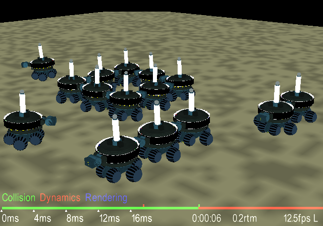
Figure 1. Swarm-bot of semi-connected
s-bots in a formation on a flat plane.
|
Simulation Environment
Swarmbot3D was developed on top of
Vortex, a commercial physics simulation engine
from Critical Mass Lab, Inc.
The simulator allows to define both robots and
worlds as XML text files. It is highly
customizable in all all its aspects. It
provides an easy to use GUI with which to
interact directly with the loaded robots and
with which to customize world definition such
as diffused light brightness, gravity pull,
egocentric camera view, resetting, etc.
|
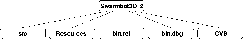
Figure 2. Swarmbot3D Tree Structure .
|
Simulator Characteristics
Swarmbot3D is a sophisticated
simulation package.
Its main characteristics can be summarized as
follows.
- Continuous 3D Dynamics. It is a
continuous 3D dynamics simulator of a
multi-agent system (swarm-bot) of
cooperating robots ( s-bot).
- Hardware S-Bot Compatibility. All
hardware functionalities
(sensors+mechanics) of one real s-bot have
been implmented.
- Software S-Bot Compatibility.
Programs developed in Swarmbot3D
are totally portable to the real robot
since they are defined in terms of a common
API.
- Interactive Control. It provides
on-line interactive control during
simulation, useful for rapid prototyping.
- Multi-Level Models. Most of the
robot simulation modules have
implementations at different levels of
detail. In this respect, 4 different
s-bot reference models have been
defined (Fast, Simple, Medium, and
Detailed).
Dynamic Model Switching. is an
extra feature unique in simulation of
complex systems such as robots. It allows
switching between representation models in
real-time.
- Swarm Handling. It has the
capability of handling a group of robots
either as independent units or in a swarm
configuration. Physical connections between
two robots are created dynamically during a
simulation and can be deactivated when the
components disband.
|
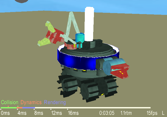
Figure 3. One detailed s-bot on a smooth plane.
|
S-bot Model definition
One of the key characteristics of
Swarmbot3D is modularity.
One s-bot has been defined in terms
of a 4 main mechanical sub-systems:
- treels,
- turret,
- front gripper arm,
- side gripper arm.
A robot model is created by declaring a
combination of these parts. Treels and turret
are compulsory, whereas front and side arms
are optional.
Each part has been defined at different levels
of details. A combination of parts can
therefore determine the robot approximation
chosen to represent one s-bot
(hierarchy).
S-Bots can easily be customized
simply by opportunely editing the XML file
containing their definition, however for a
question of convenience 4 models were
pre-packaged:
- Fast (2 driving wheels, 2 caster wheels, one
simple treels body, one turret),
- Simple(same as Fast but twice its size to
match better the real s-bot),
- Medium (6 spherical wheels, one detailed
treels body, one detailed turret, one
coarse gripper arm),
- Detailed (replica of the real s-bot
in all of its parts, mechanical and
sensorial).
|
|
|
|
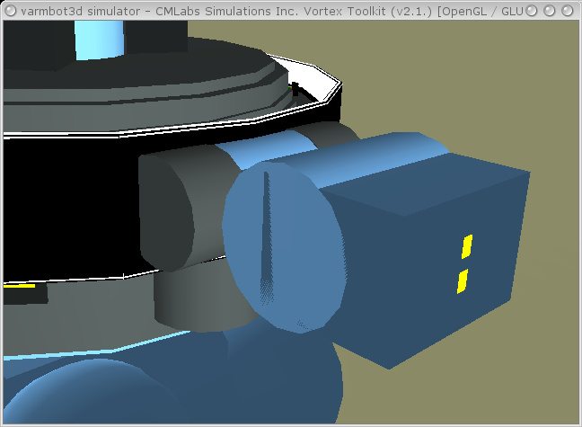
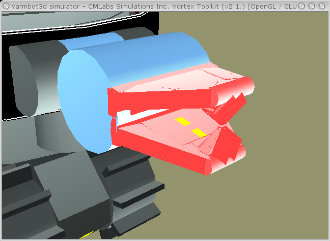
Figure 7.Gripper arm definitions
(Medium, Detailed).
|
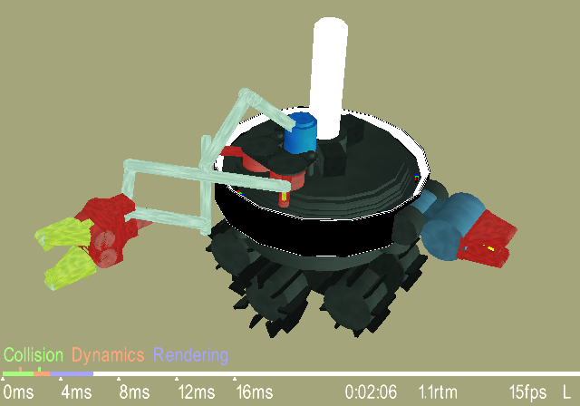
Figure 8.S-Bot detailed flexible
arm definition.
|
|
Terrain Model Definitions
Modeling terrains within Swarmbot3D
is very easy. Exactly as done with the robot
modules, they can be defined in a text based
XML format.
It is possible to define a terrain as a mere
smooth plane, as mesh surfaces, as a
composition of planes at different altitudes,
or even as combination of all of the above.
Although users can customize the terrain they
wish, for a question of convinience 3 different
terrain reference models have been
pre-packaged:
- smooth plane,
- composition of planes,
- rough terrain (mesh surface).
Every terrain definition implies a different
computational load on the simulator. The
lowest overhead is given by the smooth plane,
whereas the highest is given by a rough
terrain modeled as a mesh surface.
A terrain defined as composite planes at
different altitudes gives the same kind of
overhead of the simple plane.
The simulator underlying physics engine
(vortex) is unable to handle boolean operation
onto geometrical solids, thus it is not
possible to define holes in the ground simply
subtracting areas from it. The only way is
either defining a customized mesh surface, or
using composite planes. The latter has the
advantage over the former of implying lower
overheads.
|
|
Sensors
Each simulated s-bot is equipped with
several sensors. However, not all robot
reference models are able to host all of
them.
The Fast and Simple s-bot reference
models possess only a simple form of proximity
and sound sensors implemented as sample based
look-up table. They also possess a basic form
of effort sensor with which to read forces
acting on them.
The Medium and Detailed model possess,
instead, all the sensing capabilities of the
real robot with the exclusion of the
humitity and teperature perceptions.
The sensors available for these last two
reference models are:
- IR proximity sensors,
- ground IR sensors,
- grippers' optical barriers,
- joints encoders,
-
- force-torque sensors,
-
- light sensors,
- tachometer,
-
- sound detector,
-
- effort sensor,
- inclinometer,
- omni-directional camera.
The technique used for implementing each IR
sensors is based on ray tracing. Briefly, an
imaginary cone with amplitude matching that of
the real IR is defined. The cone is pivoted at
the location of an IR emitter around the
turret. Randomly four rays are traced from the
pivot along the cone surface and one is traced
from the pivot along the cone axis. If an
intersection of one of the 5 rays is found, a
signal is triggered.
This is a simple implementation of the real IR,
but it has proven to be sufficient for
simulating a functional approximation of them.
Ground IR sensors are implemented similarly to
the lateral IR sensors but with a much shorter
range.
|
|
|
|
Dynamic Model Switching
A unique feature of Swarmbot3D is the
possibility of dynamically switching the model
representation of one simulated s-bot.
The simulator provides a hierarchy of
reference robot models and each of them
implies a different computational overhead. By
using this technique, it is possible to force
the simulator to employ the simplest
s-bot description able to cope with
the current environment situation.
The underlying assumption is that all robot
model have to be compatible with each other.
Thanks to this technique, Swarmbot3D
is able to optimize the efficiency of a swarm
simulation by employing a model which is
always the least computationally demanding and
at the same time the most accurate among those
available in a hierarchy.
|
|
|
|